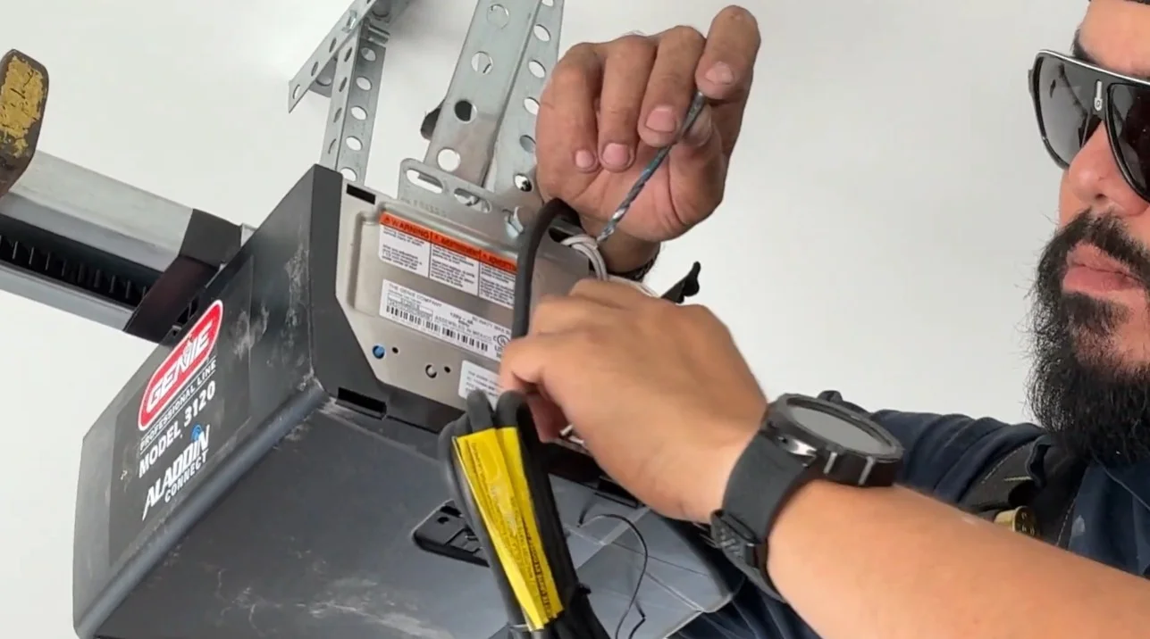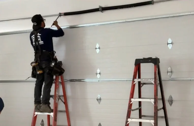







Most homeowners never think about the wires running through their garage until something stops working. But garage door opener wiring is one of the most important and most overlooked parts of the entire system. It connects your wall button, safety sensors, motor unit, and power source into one working network. When a wire is loose, corroded, or the wrong gauge, everything downstream feels the effect.
This guide walks you through the different types of wires in your opener system, what gauge and specs matter, how connections are made, and how to spot problems before they become bigger issues. Whether you are a homeowner trying to understand what a technician is telling you or someone doing your own light troubleshooting, this breakdown gives you the knowledge you need.
Why Garage Door Opener Wiring Matters More Than Most People Realize
Garage door opener wiring is what makes communication possible across your entire system. The motor does not know when to run, stop, or reverse without the correct signals reaching it through properly connected wires. The safety sensors cannot protect your family if their signal wire is damaged or too small to carry the current reliably.
Wiring problems are also notoriously difficult to diagnose without experience because they can mimic other component failures. A bad sensor wire can look like a sensor failure. A corroded wall button wire can look like a bad logic board. Understanding how the wiring works helps you and your technician narrow down the real cause faster.
If you are already dealing with other system issues beyond wiring, reviewing the full list of Garage Door Opener Parts: Fast and Easy Replacement gives you a broader picture of how everything connects.
The Two Main Wire Types in a Garage Door Opener System
Not all wires in your opener system are the same. There are two primary types, and each serves a different purpose.
Low voltage control wire
This is the wire that runs from your motor unit down to your wall control panel and to your safety sensors. It carries a low voltage signal rather than full household current. The most commonly used low voltage wire for garage door opener systems is 22-gauge, two-conductor wire. Some installations use 18-gauge for longer runs or in situations where signal reliability is a concern.
Garage door opener wire 22 gauge is the standard recommendation from most major manufacturers, including LiftMaster and Chamberlain. It is lightweight, easy to route along walls and ceilings, and inexpensive to replace if damaged.
Power supply wiring
This is the standard 120-volt household wiring that connects your opener motor unit to a wall outlet or directly to your home’s electrical panel. This type of wiring is not something homeowners should handle without electrical knowledge. It follows standard residential electrical codes and should always be inspected or installed by a qualified professional.
Garage Door Opener Wire Size: Choosing the Right Gauge
Wire gauge affects how well the signal travels from one point to another. The wrong wire size can cause weak signals, intermittent failures, or damage to sensitive components like your logic board.
22-gauge wire
This is the standard garage door opener wire size for most residential installations. It handles the low voltage signals between the motor unit, wall button, and sensors without issue on runs up to around 100 feet.
18-gauge wire
For longer runs, in larger garages, or when running wire through areas with potential interference, 18-gauge is the preferred upgrade. The lower the gauge number, the thicker the wire and the better it handles signal over distance.
What to avoid
- Use speaker wire or doorbell wire as a substitute. These are not rated for the same use and can cause inconsistent performance.
- Splicing multiple short wire pieces together to reach a connection point. Each splice is a potential failure point.
- Running control wire alongside high-voltage power cables. This can cause electrical interference that confuses your opener’s logic board.
How Safety Sensor Wiring Works
Your safety sensors are two of the most critical components in your opener system, and their wiring deserves special attention. Each sensor has two wires running back to the motor unit, typically color-coded white and white with black striping, though this can vary by brand.
According to LiftMaster’s safety sensor support article on wiring garage‑door safety sensors, the sending sensor typically has a solid amber light, and the receiving sensor has a solid green light when everything is wired and aligned correctly. If either light is off or blinking, that is a signal that something in the wiring or alignment needs attention.
Common sensor wiring problems
- A wire has been pinched under the track or bracket during installation
- The wire staples used to secure the cable were driven too tightly and cut through the insulation
- Moisture has entered a connection point and caused corrosion at the terminal
- A wire has come loose from the motor unit terminal block over time due to vibration
What to check before calling a technician
- Trace the sensor wires visually from the sensor bracket all the way to the motor unit
- Look for any visible breaks, kinks, or areas where the insulation looks damaged
- Check that both wires are firmly seated in the correct terminals on the motor unit
- Make sure no wires are pinched between a moving part and a fixed surface
Wall Control Panel Wiring: The Daily Connection
Your wall control panel connects to the motor unit via a two-conductor low voltage wire, the same 22-gauge wire used for sensors. The panel sends a simple signal to the motor unit every time you press the button, telling it to open, stop, or close.
This wire run is one of the most frequently damaged because it travels along the wall, where it can be bumped, stapled too tightly, or pulled loose by tools and vehicles moving through the garage.
What to watch for
- The wall button works inconsistently, sometimes responding and sometimes not
- The button works only when you hold it pressed rather than with a single tap
- There are visible signs of damage along the wire run on the wall
- The opener responds to remotes but not to the wall button at all
If the remote works but the wall panel does not, the issue is almost always in the wall button wiring or the panel itself, rather than the motor or logic board. This is a relatively simple and inexpensive repair for a technician.
6. Wiring Diagrams: What They Show and How to Use Them
A wiring diagram for a garage door opener is a visual map of how every wire in the system connects. Most opener manufacturers include a wiring diagram in the installation manual and also publish them on their support websites.
Common diagrams homeowners search for include the Craftsman garage door opener wiring diagram, the Genie garage door wiring diagram, and the LiftMaster garage door opener wiring diagram. While the terminal labels and wire colors may differ slightly between brands, the core layout is consistent across most residential openers.
How to read a basic wiring diagram
- The motor unit is always at the center of the diagram, with labeled terminal blocks
- Lines running to the left or right represent the sensor wires going to each side of the door
- A line running down represents the wall control wire going to the panel
- Terminal labels like “WHITE,” “WHITE/BLK,” “RED,” or numbered terminals tell you which wire connects where
If you are working from a brand-specific diagram, such as a 3-button garage door opener wiring diagram or a Craftsman door opener wiring diagram, always match the terminal labels exactly. Cross-wiring a sensor connection can permanently damage the logic board.
Torsion Spring Wire Size: A Related but Separate Consideration
When homeowners research garage door wire size, they sometimes come across the torsion spring wire size chart, which refers to the diameter of the steel wire used to manufacture torsion springs, not electrical wiring. These are two completely different things.
Torsion spring wire size is measured in fractions of an inch and determines how much weight a spring can support. This is something a technician determines based on the weight and size of your specific door. It is not something homeowners need to select or install themselves. If a technician mentions spring wire size during a service call, they are referring to the spring hardware, not the electrical system.
When to Replace Garage Door Opener Wiring
Wiring does not last forever, especially in a garage environment where temperature swings, moisture, and physical wear are ongoing factors. Here are the clearest signs that your wiring needs to be replaced rather than simply repaired.
- The insulation is brittle, cracked, or falling off sections of the wire
- You can see exposed copper along any part of the wire run
- The system develops intermittent issues that clear up on their own and then return
- There is visible corrosion at the terminal connections on the motor unit
- The wiring is more than 15 years old and was never replaced during prior repairs
Replacing control wiring is one of the more affordable service calls in the garage door industry. The materials are inexpensive, and the labor involved is straightforward for an experienced technician. Putting it off, however, can lead to sensor failures, erratic opener behavior, and in rare cases, electrical hazards.
Professional Installation vs. DIY: Knowing the Difference
Low voltage control wiring, meaning the wire between your wall button, sensors, and motor unit, is generally within reach for a capable homeowner who is comfortable with basic wiring tasks. However, there are clear situations where professional help is the right choice.
Leave it to a technician when
- You need to run a new wire through finished walls or ceilings
- Any part of the repair involves 120-volt household wiring
- You are not able to trace the fault despite visual inspection
- The opener continues to malfunction after you have replaced the visible wiring
- Your opener is still under warranty, and DIY repairs could void it
For anything beyond replacing a short run of control wire in an open garage, the cost of a professional inspection is almost always worth it. Misdiagnosed wiring faults can lead to repeated service calls and unnecessary part replacements.
If your wiring issues are connected to a broader battery or remote problem, the A Comprehensive Guide on How to Change the Battery in Your Garage Door Opener for Torrance Homeowners covers that side of the system in detail.
Preventive Wiring Maintenance Every Homeowner Can Do
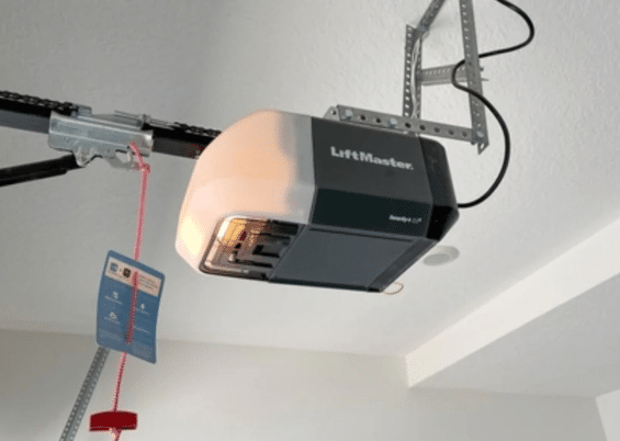
Staying ahead of wiring problems does not require any special tools or expertise. A few simple habits as part of routine garage door maintenance can extend the life of your wiring significantly and help you catch issues before they turn into failures.
- Walk the wire runs in your garage once or twice a year and look for any signs of physical damage
- Check that all wire staples securing the cable to the wall are not pressing too tightly into the insulation
- Inspect the terminal connections on the motor unit for any signs of rust or corrosion
- Keep the area around sensor brackets clear so wires are not being compressed or pulled by objects stored nearby
- After any work is done in the garage involving ladders, shelving, or wall mounting, re-check the wire runs to confirm nothing was disturbed
According to a garage‑door service and inspection checklist from Workiz, many opener‑related failures, including wiring issues, can be caught early with a simple visual inspection, making this one of the highest‑value maintenance habits a homeowner can develop.
Your Garage Door Wiring Deserves the Same Attention as the Door Itself
Garage door opener wiring is easy to overlook because it runs quietly in the background while every other part of the system gets the attention. But when the wiring fails, everything stops. Understanding the wire types, sizes, connections, and warning signs puts you in a much stronger position to catch problems early and communicate clearly with the technician handling your repair.
When you need a reliable professional to inspect or repair your garage door opener wiring, G & G Garage Door is ready to help. Our team brings hands-on experience with all major opener brands and wiring configurations, and we serve homeowners with honest, straightforward service. Give us a call at +1 (310) 782-9000 or contact us today to book your inspection.